LED Driver
Building PWM-based LED dimmer circuit and custom PCB for ambient lighting applications.

I am not an electrical engineer
While working on the Ambient Light project I had to handle the simple task of dimming an LED. The PWM signal required for this should be generated as directly as possible and without unnecessary intermediate components. The perfect exercise for training electrical skills opened up. First of all, I have to say that I am a complete beginner and have no professional background in this field. Nevertheless, I had to realize that the creation of printed circuit boards enables a much more uncomplicated planning and manufacturing process as well as reproducibility of the products. By summarizing my learnings here, I hope to be able to help other designers a little. At this point, a big thank you to Elias Mack, an actual electrical engineer who was able to help me a lot with his professional input.
What is PWM
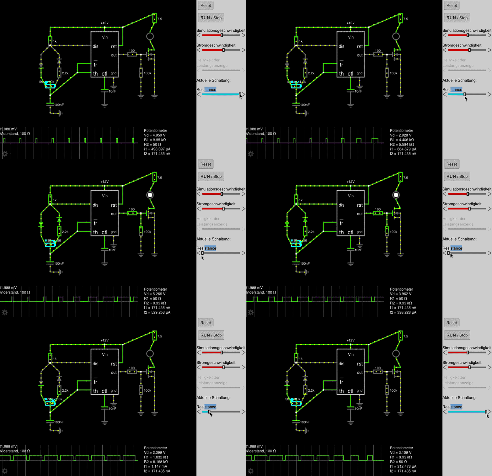
As already mentioned, dimming an LED requires a PWM signal. But what is that? It is, highly simplified, a squarewave with two discrete states. On and off. The duration of the switch-on and switch-off phase - also known as the duty cycle - can be controlled using a potentiometer. To generate this signal we will build an astable multivibrator with a NE555 timer-ic at the core. With the help of common resistors, some capacitances and a 10kΩ potentiometer we will build our circuit as shown in the CircuitJS sketch below. Going into details would be beyond the scope of this article, but if you want to know more, there's more to it here.
To limit the maximum duty cycle, we have built in a 2.2kΩ resistor. Depending on the application, this resistance might not be necessary. In this case, the output signal is sent to a driver stage which lets the current to the LED via a Mosfet. Depending on the use case, the structure of the driver stage can of course vary. The LED dropping resistor, which in our case is 7.5kΩ, should also be adapted to the consuming device. E.G. If a DC motor is controlled, an H-bridge should be used…
Printing the PCB
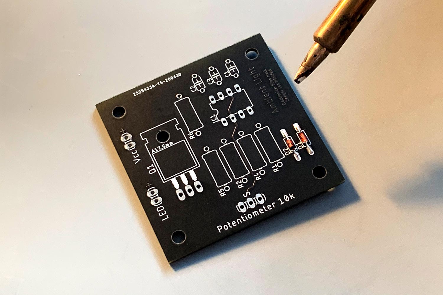
After choosing the right components and testing the circuit on a breadboard, we can either choose to solder the components onto a perfboard or to produce a printed circuit board. The advantage of a printed circuit board is that soldering the components can be done more easily and reproducibility is better. If possible, these boards should be manufactured regionally. Gerber files can for example be created with the Autodesk® software Eagle.

Soldering the Components
To solder the components onto the board, you need steady hands, a soldering iron (preferably with temperature control), lead-free solder, desoldering braid and, if you feel like it, a circuit board holder. Heat up your soldering iron to the temperature specified on your solder. Low components come first. The components are bent to the correct hole size with the help of a bending gauge and are then inserted as far as possible. With the component in place, bend the small wire legs to prevent the component from sliding out. Now turn the circuit board and heat the copper pad on the underside of the circuit board for about three seconds. Bring solder to the solder point and wait for the tin to wrap around the pin of the component and the copper plate. Now pull away the solder and – shortly afterwards – the soldering iron. Wait until the spot has cooled down, pinch off the excess wire, and you're done! I am a complete beginner myself and had a lot of help from Elias Mack on this project. Fortunately, there are plenty of tutorials out there.


Done!
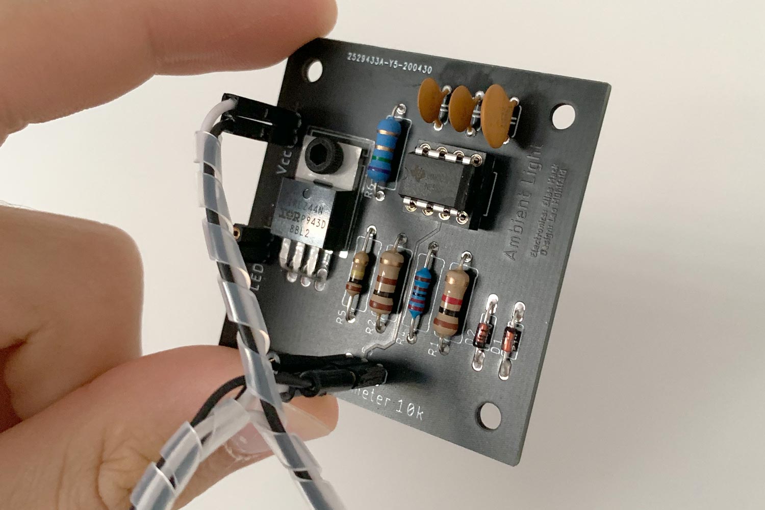
All you have to do is connect all external components such as potentiometer, LED and power source to the board. You do now have a reliable and reproduceable circuit.